Help:Manual Editshapes: Difference between revisions
(Created page with "Category:Help_Manual Table of Contents <h2>Editing Shapes</h2> Many of the objects that can be incorporated into a Scribus document are vector drawings, and a...") |
No edit summary |
||
| Line 14: | Line 14: | ||
<h3>Finally: What is a Contour Line?</h3> Or maybe we should say, what is it for? A contour line is itself never visible, except in this editing mode. Let's imagine you have a frame/shape which is not rectangular, and you wish to flow around it, but not necessarily follow the contours of the frame/shape. Even if it's a shape and has a bounding box, as we saw above sometimes the bounding box is not what we want either, therefore we can use a contour line to flow in our precisely desired way. While you are editing your contour line, you will see the text flow change to help you get the look you want. <table cellpadding="3"> <tr> <td>[[File:Help_frame_shape_flow.png]]</td> <td>[[File:Help_contourline_flow.png]]</td> </tr> </table> <p>Contour lines are not considered part of the graphic components, so therefore its nodes and control points can be outside the bounding box.</p> <h3>Combining Polygons</h3> This operation really applies to both polygons and shapes, and mixtures of the two. The idea is to combine 2 or more shapes on different levels into a single one. <table cellpadding="3"> <tr> <td>[[File:Help_combine_polygons.png]]</td> <td>[[File:Help_combine_polygons1.png]]</td> <td>[[File:Help_combine_polygons3.png]]</td> </tr> </table> This top row shows our starting point, with a shape overlapping a polygon, the shape having some transparency. In the middle, we select both by click-dragging the mouse around them, then select <b>Item > Combine Polygons</b> from the menu, to get what we see on the right. With this method, the colors derive from the bottom object. <table> <tr> <td>[[File:Help_combine_polygons2.png]]</td> <td>[[File:Help_combine_polygons4.png]]</td> <td>[[File:Help_combine_polygons5.png]]</td> </tr> </table> In the left graphic here, we selected the shapes by holding down Shift and clicking the cross shape first, then combined, so even if you combine more than two shapes this way, the colors derive from the first one clicked. The middle shows that our combined polygon has retained the transparency. On the right, we see the results of <b>Item > Split Polygons</b>. It is not recommended to Undo combined polygons, since results are unpredictable and may cause a subsequent crash, depending on what you do next. <p>Something else to point out here is that in the bottom row, the leftmost combination uses an <b>Even-Odd Fill Rule</b> from the Shape tab, and the middle uses <b>Non Zero</b>. <i>You apply the fill rule after you combine polygons</i>.</p> | <h3>Finally: What is a Contour Line?</h3> Or maybe we should say, what is it for? A contour line is itself never visible, except in this editing mode. Let's imagine you have a frame/shape which is not rectangular, and you wish to flow around it, but not necessarily follow the contours of the frame/shape. Even if it's a shape and has a bounding box, as we saw above sometimes the bounding box is not what we want either, therefore we can use a contour line to flow in our precisely desired way. While you are editing your contour line, you will see the text flow change to help you get the look you want. <table cellpadding="3"> <tr> <td>[[File:Help_frame_shape_flow.png]]</td> <td>[[File:Help_contourline_flow.png]]</td> </tr> </table> <p>Contour lines are not considered part of the graphic components, so therefore its nodes and control points can be outside the bounding box.</p> <h3>Combining Polygons</h3> This operation really applies to both polygons and shapes, and mixtures of the two. The idea is to combine 2 or more shapes on different levels into a single one. <table cellpadding="3"> <tr> <td>[[File:Help_combine_polygons.png]]</td> <td>[[File:Help_combine_polygons1.png]]</td> <td>[[File:Help_combine_polygons3.png]]</td> </tr> </table> This top row shows our starting point, with a shape overlapping a polygon, the shape having some transparency. In the middle, we select both by click-dragging the mouse around them, then select <b>Item > Combine Polygons</b> from the menu, to get what we see on the right. With this method, the colors derive from the bottom object. <table> <tr> <td>[[File:Help_combine_polygons2.png]]</td> <td>[[File:Help_combine_polygons4.png]]</td> <td>[[File:Help_combine_polygons5.png]]</td> </tr> </table> In the left graphic here, we selected the shapes by holding down Shift and clicking the cross shape first, then combined, so even if you combine more than two shapes this way, the colors derive from the first one clicked. The middle shows that our combined polygon has retained the transparency. On the right, we see the results of <b>Item > Split Polygons</b>. It is not recommended to Undo combined polygons, since results are unpredictable and may cause a subsequent crash, depending on what you do next. <p>Something else to point out here is that in the bottom row, the leftmost combination uses an <b>Even-Odd Fill Rule</b> from the Shape tab, and the middle uses <b>Non Zero</b>. <i>You apply the fill rule after you combine polygons</i>.</p> | ||
{{OPL}} | |||
Latest revision as of 18:30, 29 March 2012
Editing Shapes
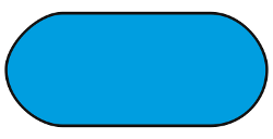
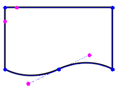
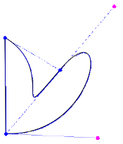
Many of the objects that can be incorporated into a Scribus document are vector drawings, and as such can be edited. Even though the title seems to refer to the geometric shapes that can be easily created, the same procedures can be applied to all of these:
- Shapes
- Polygons
- Frames - all types
- Contour lines
- Bézier curves
- Freehand lines
- Outlines created from text glyphs
- Imported vector drawings, such as EPS and SVG
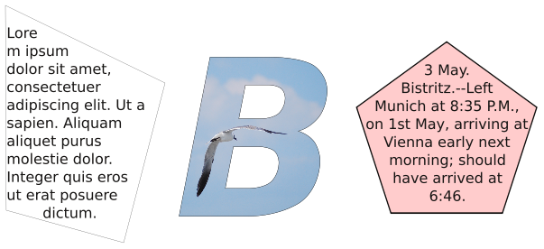
As you may be aware or recall, when you consider the ability to convert from one kind of object to another, there is a great deal of flexibility in what you can do. Here we have edited the shape of a text frame, then taken a large glyph, converted to an outline, then converted to an image frame, and finally we take a polygon and convert to a text frame. The final state of the object determines its editing capabilities, so the large B can be edited like any other image frame, the polygon can have its text edited in Story Editor.
< |
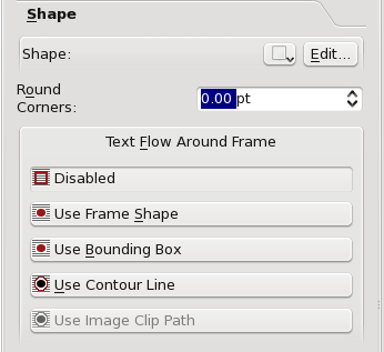
Properties: Shape
Edit Button
Skewing
Rotating, Enlarging, Shrinking
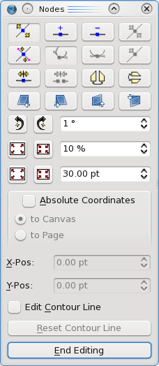
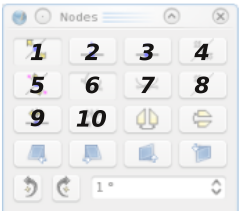
Below the 4 rows of buttons we have spinboxes paired with buttons to the left. These are quite intuitive and the two buttons are complementary actions, for rotation, and then two ways to enlarge and shrink, either by percentage or number of points. Each click produces the amount of change indicated in the spinbox.
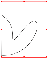
What is a Bounding Box?
Finally: What is a Contour Line?
Or maybe we should say, what is it for? A contour line is itself never visible, except in this editing mode. Let's imagine you have a frame/shape which is not rectangular, and you wish to flow around it, but not necessarily follow the contours of the frame/shape. Even if it's a shape and has a bounding box, as we saw above sometimes the bounding box is not what we want either, therefore we can use a contour line to flow in our precisely desired way. While you are editing your contour line, you will see the text flow change to help you get the look you want.
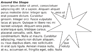 | 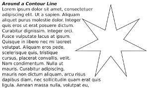 |
Contour lines are not considered part of the graphic components, so therefore its nodes and control points can be outside the bounding box.
Combining Polygons
This operation really applies to both polygons and shapes, and mixtures of the two. The idea is to combine 2 or more shapes on different levels into a single one.
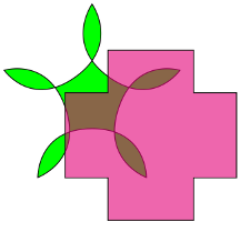 | 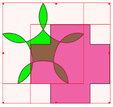 | 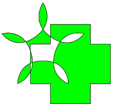 |
This top row shows our starting point, with a shape overlapping a polygon, the shape having some transparency. In the middle, we select both by click-dragging the mouse around them, then select Item > Combine Polygons from the menu, to get what we see on the right. With this method, the colors derive from the bottom object.
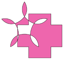 | 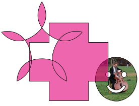 | 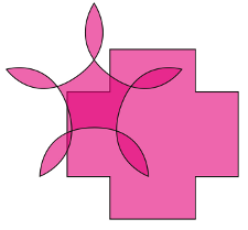 |
In the left graphic here, we selected the shapes by holding down Shift and clicking the cross shape first, then combined, so even if you combine more than two shapes this way, the colors derive from the first one clicked. The middle shows that our combined polygon has retained the transparency. On the right, we see the results of Item > Split Polygons. It is not recommended to Undo combined polygons, since results are unpredictable and may cause a subsequent crash, depending on what you do next.
Something else to point out here is that in the bottom row, the leftmost combination uses an Even-Odd Fill Rule from the Shape tab, and the middle uses Non Zero. You apply the fill rule after you combine polygons.
| This material may be distributed only subject to the terms and conditions set forth in the Open Publication License, v1.0 or later. Distribution of the work or derivative of the work in any standard (paper) book form is prohibited unless prior permission is obtained from the copyright holder. A copy of the license is included in the section entitled "Text of the Open Publication License." |
