Bezier Curve Basics - Part 1 - Simple Geometric Shapes
| Installation • Usage • PDF issues • Imposition • Other |
Button … Menu → Choice … Keyboard
Introduction
You might have tried using the Bezier Curve tool in Scribus. You might also have been able to get it to produce some lovely curves. And, if so, that's great and you don't need any more help.
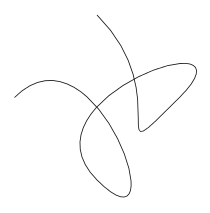
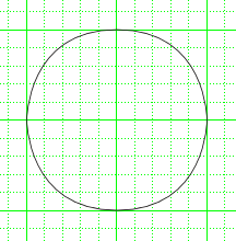
On the other hand, it's more likely that you were totally confused and never managed to create anything other than a messy squiggle. The drawing on the right shows an approximation of the author's first attempt at creating a circle using the Bezier Curve tool without trying to understand it first. Not very pretty is it?
If your attempts at using the Bezier Curve tool are similar to that of the author's first attempt then this tutorial is for you. It won't make you a curve master but your bezier-fu will be a little stronger.
Setup
- Open Scribus and create a new document. (A4/Letter portrait will do.)
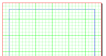
First, you should display the grid and set grid snapping on. This is important because it will allow you to create the shapes much easier than otherwise.
- Choose menu File → Document Setup
- Select "Guides" from the scrolling list on the left.
- Check the "Show Page Grid" icon.
- Set the "Major Grid" Spacing to 100pt.
- Set the "Minor Grid" Spacing to 20pt.
- OK the dialog.
- Choose menu Page → Snap to Grid. If "Snap to Grid" was already ticked then don't select it, leave it ticked.
Your document should look like figure 1.
Your First Curve
An important thing to know about using bezier curves is that you cannot create all possible shapes in just one go. The bezier curve tool follows certain rules - which are outside the scope of this tutorial - when you draw with it and you need to "go with the flow" and not try anything too fancy or complicated.
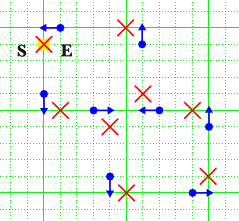
This tutorial follows certain conventions that make it easier to demonstrate what you need to do by way of diagrams.
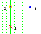
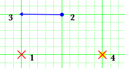
Looking at figure 2:
- A red cross indicates a point where you need to click the left-hand mouse button and then release (just a normal click).
- A blue arrow indicates that you should depress the left-hand mouse button at the end of the arrow with the dot, keeping the mouse button pressed down, and drag the pointer until you reach the end with the arrow head, where you should then release the mouse button (a drag).
- The yellow square indicates that you should right-click to finish drawing the curve. It does not matter where the mouse pointer is when you right-click.
- The numbers next to the shapes represent the order in which you should perform the actions.
So, for instance, in figure 2:
- The first action is to click on the bottom-left corner of the square.
- Then drag from the top-right to the top-left.
- Then right-click to finish.
Now you can try it.
- Choose menu Insert → Insert Bezier Curve. Or you can select the Bezier Curve tool from the toolbar.
- Follow the actions in figure 2.
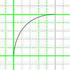
You should now have a simple arc - like a quarter of a circle - the same as figure 3.
So what's just happened?
What you have done is tell Scribus where to start drawing a curve from (point 1), where to draw the curve through (point 2), and a position (point 3) marking how you want the curve to be drawn.
When Scribus draws curves it uses things called Control Points which tell it how to shape the curve. In the case above, the only control point was at position 3 (the end of the drag). This is better explained in the next section where you'll draw a full curve.
A Full Curve
Now you'll draw a full curve and things will start to become a bit clearer.
- Choose menu Insert → Insert Bezier Curve. Or you can select the Bezier Curve tool from the toolbar.
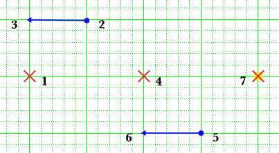
- Follow the actions in figure 4.
You should have produced a half-circle that looks like figure 5.
You probably noticed that the "free end" of the curve was waving around with the mouse pointer, see the dotted line in figure 6. This was because Scribus was continually trying to calculate where the last part of the curve should be drawn. You might also have noticed that, no matter where you moved the mouse pointer, the curve always seemed to "follow" some already chosen direction. This is because of the control points.
And here is where things get a little technical, so brace yourself.
So what's just happened?
- Double-click the half-circle you just created.
You're now in the ![]() Node Editor and a new dialog box should have appeared. Don't worry if you've not used this before, you're only in here to look at the control points and you'll be leaving soon.
Node Editor and a new dialog box should have appeared. Don't worry if you've not used this before, you're only in here to look at the control points and you'll be leaving soon.
In figure 7 you can see how the half-circle curve you created was constructed. You can see at the bottom-left where you clicked to start the curve (where the blue dot is) and this is called a node. A node is simply a point where Scribus draws a curve through.
You can also see, at the top, where you dragged from one place to another. The start of the drag created the second node and the end of the drag created a pink dot (marked A). This pink dot is called a Control Point. As mentioned before, the control points tell Scribus how to draw the curve through the other points you've chosen (the nodes).
On the right you can see the node at the bottom-right where you clicked last but there's also another pink control point that you didn't create (marked B). It was Scribus that created this new control point, and it created it as the "mirrored double" of the first control point.
It did what now??? I'll try and explain.
When you dragged from point 2 to point 3 - see figure 4 to refresh your memory - you told Scribus where to create the first control point but you also - by dragging in the direction you dragged - gave it a direction in which to mirror the first control point through the second node to create the second control point. This mirroring took place at a right angle to the "line" you made by dragging from point 2 to point 3 - see the purple dotted line in figure 8.
This concept takes some time to get used to and the best way to understand it is to practice drawing some curves but dragging from point 2 to point 3 at different angles. Try creating more curves but change the angle of the drag, then open the Node Editor to see where the control points have been created.
Once you've got you head around the concept you're ready to try some more complicated curves.
Close the Node Editor by pressing End Editing if you haven't already done so.
Coming Full Circle
Now it's time to try making some more useful - or at least interesting - shapes, starting with a circle.
- Choose menu Insert → Insert Bezier Curve (or select the Bezier Curve tool from the toolbar).
- Follow the actions in figure 9 to get the result in figure 10.
Did you notice how, by dragging in a different direction the second time, you changed the direction of the second curve? Once you've finished a full curve you can go in any direction you want.
Making Waves
This time you'll draw a wavy line.
- Choose menu Insert → Insert Bezier Curve (or select the Bezier Curve tool from the toolbar).
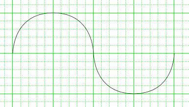
- Follow the actions in figure 11 to get the result in figure 12.
Did you notice that you can change the direction of the curve?
Ghost in the Machine
Now it's time for a little fun making a Pac Man ghost.
- Choose menu Insert → Insert Bezier Curve (or select the Bezier Curve tool from the toolbar).
- Follow the actions in figure 13. The numbers have been omitted from the bottom of the diagram to stop it getting messy but you should be able to figure out which way to go.
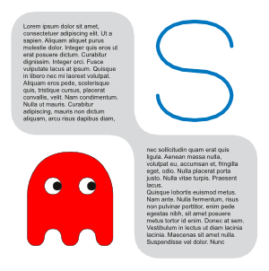
You can then give the ghost a fill colour, draw some eyes using the circle techniques shown earlier, and you'll get something like that in figure 14. (The pupils of the eyes are just smaller duplicates of the whites of the eyes.) Don't worry if you can't draw all of the ghost, it's not important for the tutorial. It's the curves that are important.
As you can see, you can use these very simple techniques you've learned to make shapes easily.
Making it Useful
Okay, you might be saying to yourself (or to whoever's in the room with you), so I can draw circles but Scribus already has a Circle tool, and I can draw a Pac Man ghost but where am I going to use that? And you'd be correct. The things you've drawn so far aren't very useful but they show you the sort of thing you can do. And now you're going to draw some much more useful things.
Rounded Rectangles
Rounded rectangles are very useful and you can create them by drawing a normal rectangle shape and using the Scribus rounding function (in "Properties / Shape") but you can also draw your own using bezier curves.
- Choose menu Insert → Insert Bezier Curve (or select the Bezier Curve tool from the toolbar).
- Follow the actions in figure 15 to get the result in figure 16.
While this is all well and good, what about more complex shapes? Ask and you shall receive.
Rounded Shapes
You can draw almost any rounded shape you like using bezier curves.
- Choose menu Insert → Insert Bezier Curve (or select the Bezier Curve tool from the toolbar).
- Follow the actions in figure 17. Start from the S (start) and work clockwise to the E (end).
You should get the result as in figure 18. It's quite easy once you know how, don't you think?
Conclusion
Congratulations honoured student, you have now attained the level of White Belt in the ancient art of Bezier-fu.
Exercises
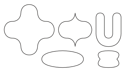
Just for fun, how many of the shapes below can you make? All can be created using a single bezier curve with the techniques shown above.
