How to create an RSS Feed Symbol
| Installation • Usage • PDF issues • Imposition • Other |
Button … Menu → Choice … Keyboard
Introduction
This tutorial will show how you can create an RSS Feed symbol using only the tools in Scribus.
You probably wouldn't use Scribus to do this as there are many much better images available free to use but this tutorial is mainly about using the Scribus tools.
Some of the techniques used here are a bit tricky but there's nothing too difficult, it can just be quite a lot of work for something that looks simple.
Colours
- Open Scribus and create a new document. (A4/Letter of any orientation will be fine.)
You'll need two colours:
- Light Orange - CMYK: 0%, 50%, 100%, 0%
- Dark Orange - CMYK: 5%, 60%, 90%, 10%
Use the ![]() Color Editor - menu Edit → Colors… - to add these to your document.
Color Editor - menu Edit → Colors… - to add these to your document.
If you don't know how to do this see the Scribus Help Manual via the Help menu, section "Documentation / Editing Colors". If you don't have this manual installed, look at the "Colours" section on this other tutorial. If you're still struggling, try asking about it on the Scribus Forum.
Background
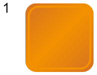
Now you'll need to create the background rounded square shape as in figure 1.
This bit is fairly easy.
- Create a square. (If you're following along I've made it 100pt width/height.)
- Using
 Properties ⟩⟩ Shape set the corner to rounded. (E.g. 16pt.)
 - Set the Line Colour to "None".
- Set the Fill Colour type to "Diagonal Gradient".
- Set the left-most gradient stop to Dark Orange at position 0%.
- Set the right-most gradient stop to Dark Orange at position 100%.
- Create a new gradient stop at 50% and set it to Light Orange.
- Select the rounded square and choose menu Item → Transform…
- Press the Add… button and choose "Scaling" from the menu.
- Set both Horizontal and Vertical scaling to 90%.
- Select the centre of the object as the origin.
- Set the number of copies to "1" and press OK
- Select the new smaller rectangle and set its Fill Type to "Normal" and its Fill Colour to "None".
- Set the Line Colour to Light Orange and give it a Line Width of 3pt.
You should now have a similar shape to that in figure 1.
The Circles
This is a bit harder than it might seem at first.
- Create a circle to be the outside of the bigger "quarter pipe". (I've used 140pt).
- Choose menu Item → Transform…
- Press the Add… button and choose "Scaling" from the menu.
- Set both Horizontal and Vertical scaling to 80%.
- Select the centre of the object as the origin.
- Set the number of copies to "1" and press OK
- Select the new smaller circle and follow steps "Choose menu" to "Set the number" above but use a scaling percent of 76%.
- Select the even newer even smaller circle and follow steps "Choose menu" to "Set the number" above again but use a scaling percent of 66%.
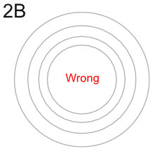
Using these percentage amounts should give you something that looks like figure 2A.
The Doughnuts
Now you need to make the four circles into two doughnut shapes.
- Select the inner-most smallest circle and shift-select the next largest one.
- Choose menu Item → Path Tools → Path Operations…
- Select the "Subtracts" operation (and swap the shapes round if you need to see the doughnut shape in the top-right preview box).
- Press OK
- Select the outer-most largest circle and shift-select the next smaller circle.
- Repeat steps "Choose menu" to "Press OK" above.
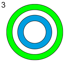
You should now have two doughnuts instead of four circles. Figure 3 is coloured so you can see the result better but if you do that yourself remember to undo before continuing.
The Quarter Pipes
This is the tricky bit.
- Choose menu Insert → Insert Bezier Curve (or use any of the relevant shortcuts).
- Click above the top-middle of the large doughnut, then click below the bottom-middle, and right-click to close the curve.
You'll need to be careful to make the line vertically straight but you can use the ![]() Align & Distribute palette to align centrally. (You can't use the normal Line tool as normal lines can't cut polygons, but more on that soon.)
Align & Distribute palette to align centrally. (You can't use the normal Line tool as normal lines can't cut polygons, but more on that soon.)
- Choose menu Item → Multiple Duplicate and press the OK button to create a duplicate on top of the original.
- Select one of the straight lines and shift-select the smaller doughnut.
- Choose menu Item → Path Tools → Cut Polygon
The bezier line has now vanished - although leaving the other one - and the doughnut has been split in two. You might be able to see where it's been split by the slightly thicker looking lines at certain places.
- Select the remaining bezier line, shift-select the larger doughnut, and choose menu Item → Path Tools → Cut Polygon again.
Your doughnuts have now been split into two "half pipes". In figure 4 they've been moved slightly so you can see but you shouldn't do this.
Now you need to split them again.
- Draw another bezier line as you did is step 2 but make it horizontal across the middle of the half pipes.
- Use Multiple Duplicate again to get another one.
- Select one of the bezier lines and one of the right-hand half pipes and use the Cut Polygon function again.
- Do the same for the other bezier line and the other right-hand half-pipe.
You can try doing the "cut" quicker by drawing an "L" shape to do the cutting instead of two straight lines but you might find that it's more difficult to get the centre alignments right. You can try though.
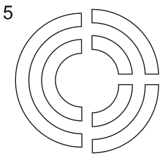
You should now have one half pipe on the left and two "quarter pipes" on the right. In figure 5 they've been moved slightly so you can see.
Putting it all together
You can now delete the left-hand half pipes and the bottom set of quarter pipes as they're not needed.
- Draw a small circle. (For example, 16pt width/height.)
- Select the circle and both quarter pipes and, using the
 Align & Distribute palette, align them all to their left-hand sides and bottoms.
 - Give the circle and quarter pipes a Line Colour of "None" and a Fill Colour of White.
- Group them all together so they're easier to move around.
- Move the white shapes over the original rounded squares (remember creating them?!).
You'll can use the ![]() Align & Distribute palette for a quick placement or you might want to place them manually as is your preference.
Align & Distribute palette for a quick placement or you might want to place them manually as is your preference.
Conclusion
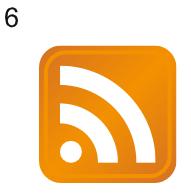
You should now have figure 6, and you're done. Phew.
It's quite a lot of work for something that's pretty simple but hopefully you've get more of an idea about how some of Scribus' functions work, and that's the main thing.

